Creating a CCU10 puzzle from tin using a laser cutting machine
The CCU10 puzzle CCU10 (Computer's Choice Unique 10) is a 6-piece burr
puzzle that was discovered by Bill Cutler using a computer. It has
one solution and removing the first piece requires 10 moves. This
document describes making CCU10 from tin. The length of each piece is
about 49.3mm.
The project was inspired by a similar project by Oskar van Deventer,
where Oskar and I used my laser cutting machine to create molds for
pieces of Oskar's edge slide puzzle design.
Used Materials
-
Tin (about 0.4kg) (about 0.25kg is used in the puzzle) Tin can be
bought in several kinds. I used tin that is food-safe; it is safe
to use in cups and plates.
- 4mm MDF (a piece of 20cm by 20cm) (can be re-used)
- 6.2mm MDF (a piece of 20cm by 20cm) (destroyed)
- 200 gram / square m paper (a piece 10cm by 20cm)
- 14 bolts M3x25 (that is 3mm thick with 25mm of thread) + 14 nuts
Required tools
- Gas stove
- Small pan (not suitable for cooking food after melting tin)
- Steel brush
- File
- Small metal saw
- Some knives, screwdrivers, etc. (to remove the mold).
- Safety goggles
- Laser cutting facility
Laser cutting the mold
The laser cutting machine is an expensive device. Mine uses a 35Watt
laser which can be directed straight downward on any point of a 30cm
by 60cm surface. The machine is connected to a personal computer
running MS-Windows. To the operating system the laser cutting machine
looks like a printer. Naturally you also need a design to cut and
software that "prints" the design to the laser cutting machine.
I use self-written software, but it can also be done from AutoCad,
CorelDraw, etc.
When the laser cutting machine is cutting 6mm MDF, it removes a slot
that is about 0.1mm wide at the bottom surface and about 0.3mm wide
at the top surface of the MDF. The cut surfaces are charred but
quite smooth. To ensure that the pieces actually fit together, the
cuts from the MDF must be completely inside the
lines of the grid in which all edges of the pieces fall.
Because the thickness of my MDF stock was 6.2mm, my unit size is
6.2mm. I've made all cuts that outline the pieces 0.2mm inside this
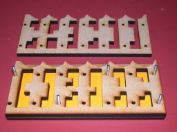
grid. The main layers of the mold are shown below:
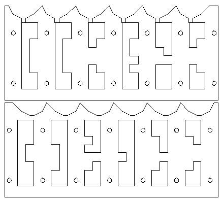
Do not use this drawing to make your own. The
resolution is simply too low. You really need the drawing in a
vector format.
The layer shown on the bottom should be turned over and then placed
on top of the layer shown above it.
To ensure that air can escape from the mold when the tin is cast
into it, a layer of 200 grams per square meter paper is cut using
the design shown below.
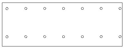
This paper has the same mounting holes as the MDF. The bottom edge
goes flush with the bottom edge of the other layers of the mold. The
top edge is about 0.2mm below the top of the shapes. This creates a
narrow channel for the air to escape (and a sharp edge on the
resulting pieces that can be filed off in a second). The amazing
thing is that the paper can be reused a couple of times.
Finally two covers are needed. These are cut from 4mm MDF, but the
thickness is not very relevant. If you use thicker MDF for the
covers, you'll need longer bolts to hold the mold together. The
layout for the front and back covers is the same and shown below.
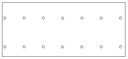
This is virtually identical to the paper layer, except that the top
edge is further above the top row of mounting holes.
Cutting the layers of the mold
All layers (including the paper one) are made with the laser cutting
machine. The photo below shows the result of cutting the two 6.2mm
pieces. Click on any of the photos for a really large version.
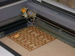
After the MDF is taken out of the machine, the cut out pieces can
be removed.

All layers of the mold (4mm MDF, paper, 6mm MDF, 6mm MDF, 4mm MDF)
are stacked together and aligned using five M3x25 bolts. I've
wrapped some Scotch tape around the shafts of these bolts to make
them fit snugly in the holes. This reduces the possibility for
mis-alignment to the minimum. (The other 9 bolts are put in later
and need not be wrapped with tape.) I used yellow paper.
A close up of the top of the assembled mold is shown below.
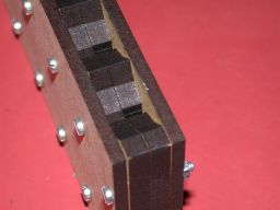
The top of the mold show the holes where the tin will be poured
in. The nuts on the bolts must be hand-tight; no tools are
required to tighten them.
Pouring the tin
The tin is heated in a small aluminum pan. The melting point of
the aluminum is much higher than the melting
point of the tin; there is little risk of melting the aluminum
of the pan. A gas stove is required to melt the tin.
Melting and pouring tin should be done with great care. This is
not something to be done by unsupervised children.
I have no photographs of the pouring process because I did this
all on my own and I couldn't take photographs while pouring.
I put a clamp on the mold to make it more stable before I poured
the tin. I slowly poured tin into the entry holes until they
overflowed, or were on the verge of overflowing. I wore safety
goggles while pouring the tin. The tin won't sputter when being
poured in a nice dry mold, but one should never take chances
with one's eyesight.
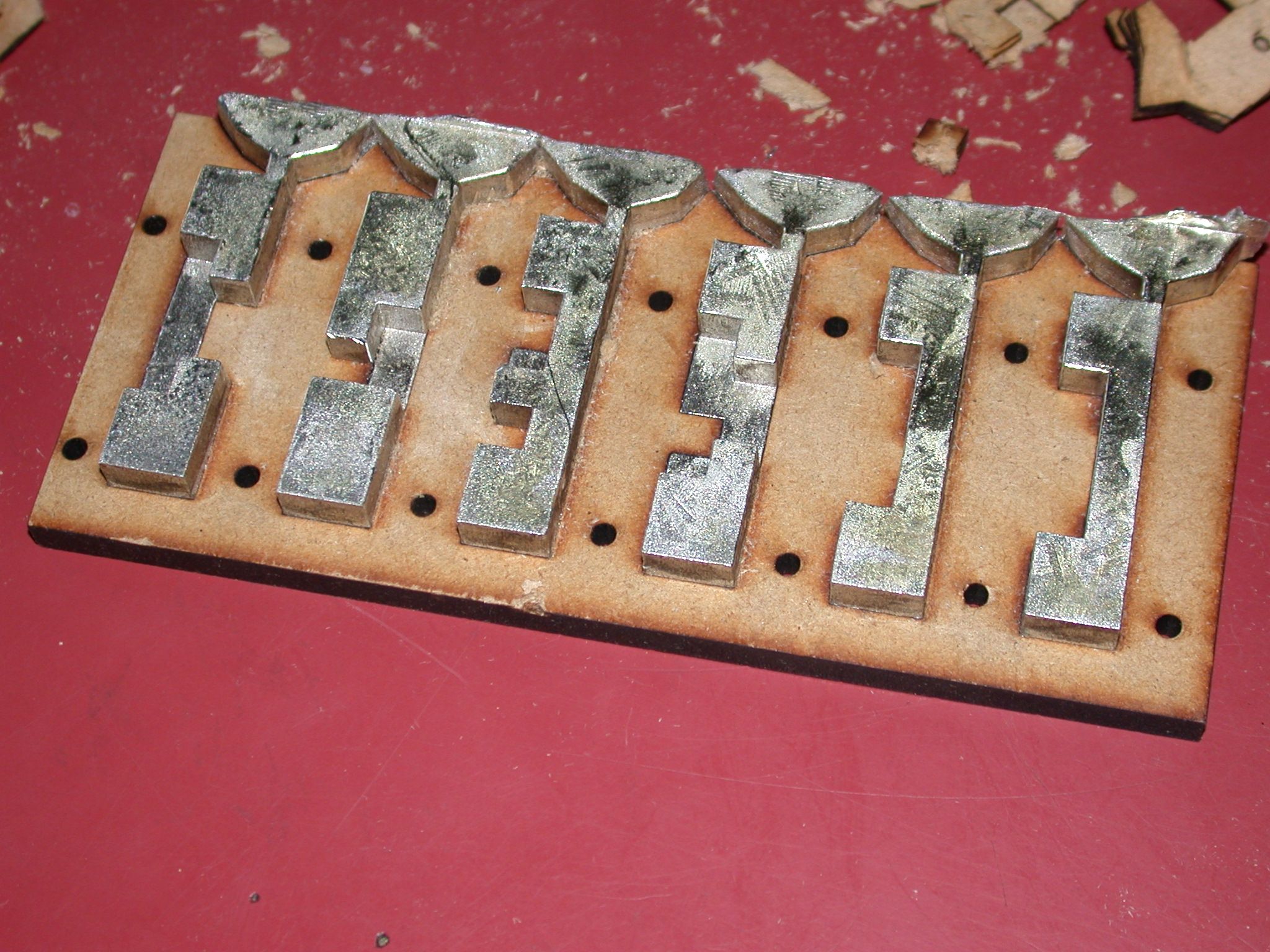
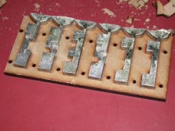
Opening and removing the mold
After pouring I waited some time to let the tin solidify and
cool down. After removing the bolts and taking off the
top cover I had the following result.


As you can see, the tin filled the mold very precisely.
It was not possible to remove the 6.2mm MDF layers of the mold
from the tin without completely destroying them. I used a knife
and a big screwdriver to carefully destroy the mold around the
pieces without damaging the pieces. (In later, similar projects,
I used the laser cutting machine to cut the wood of the mold in
small bits; the laser won't damange the tin.) After removal of
the first layer of the mold, the result looked like this.
The second layer is removed.
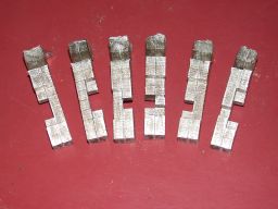
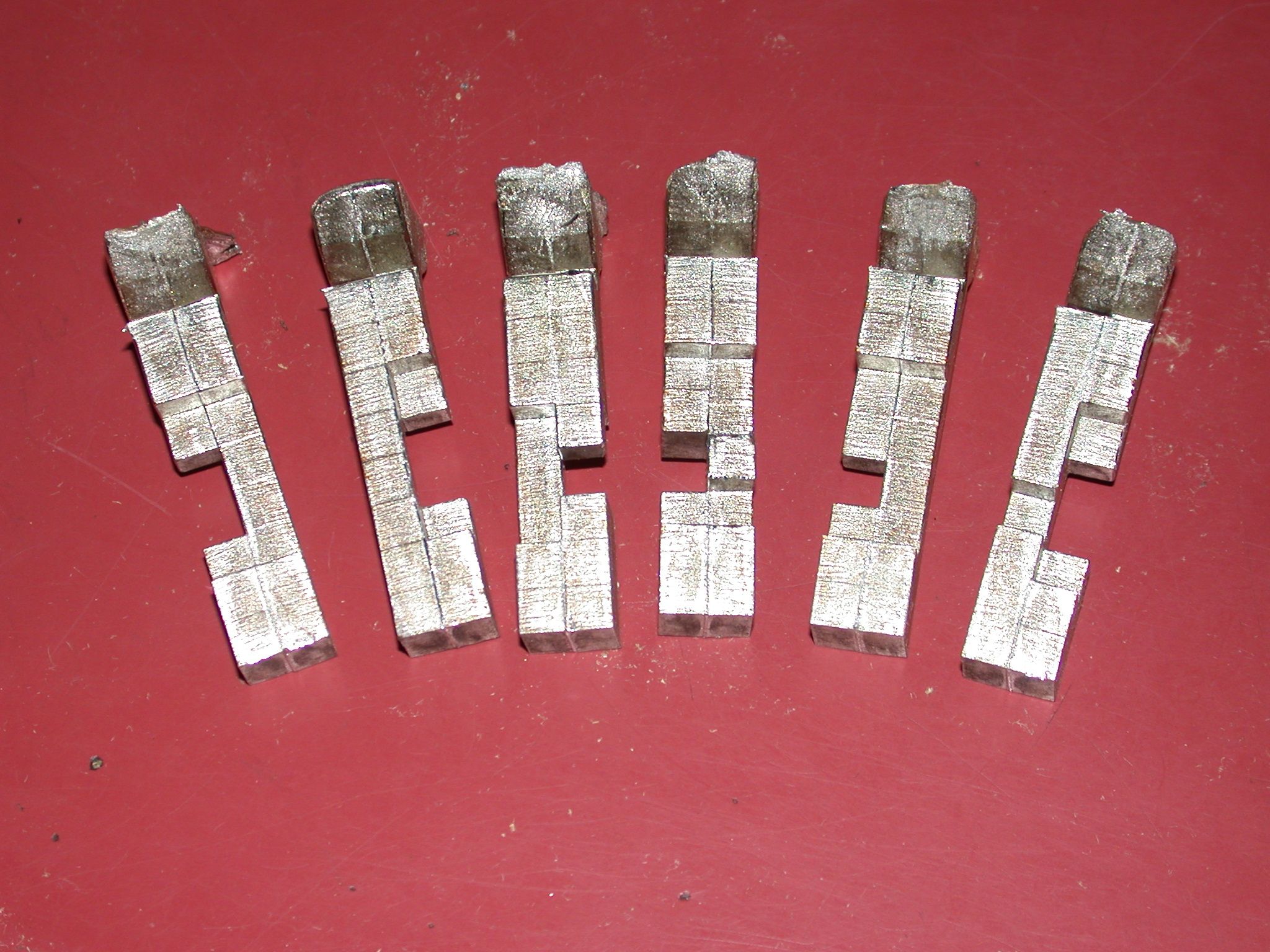
Removing the cast-entry points
I removed the cast entry points with a simple small metal saw and
filed off the remaining stumps. Tin is a soft metal that can
easily be sawn and filed.

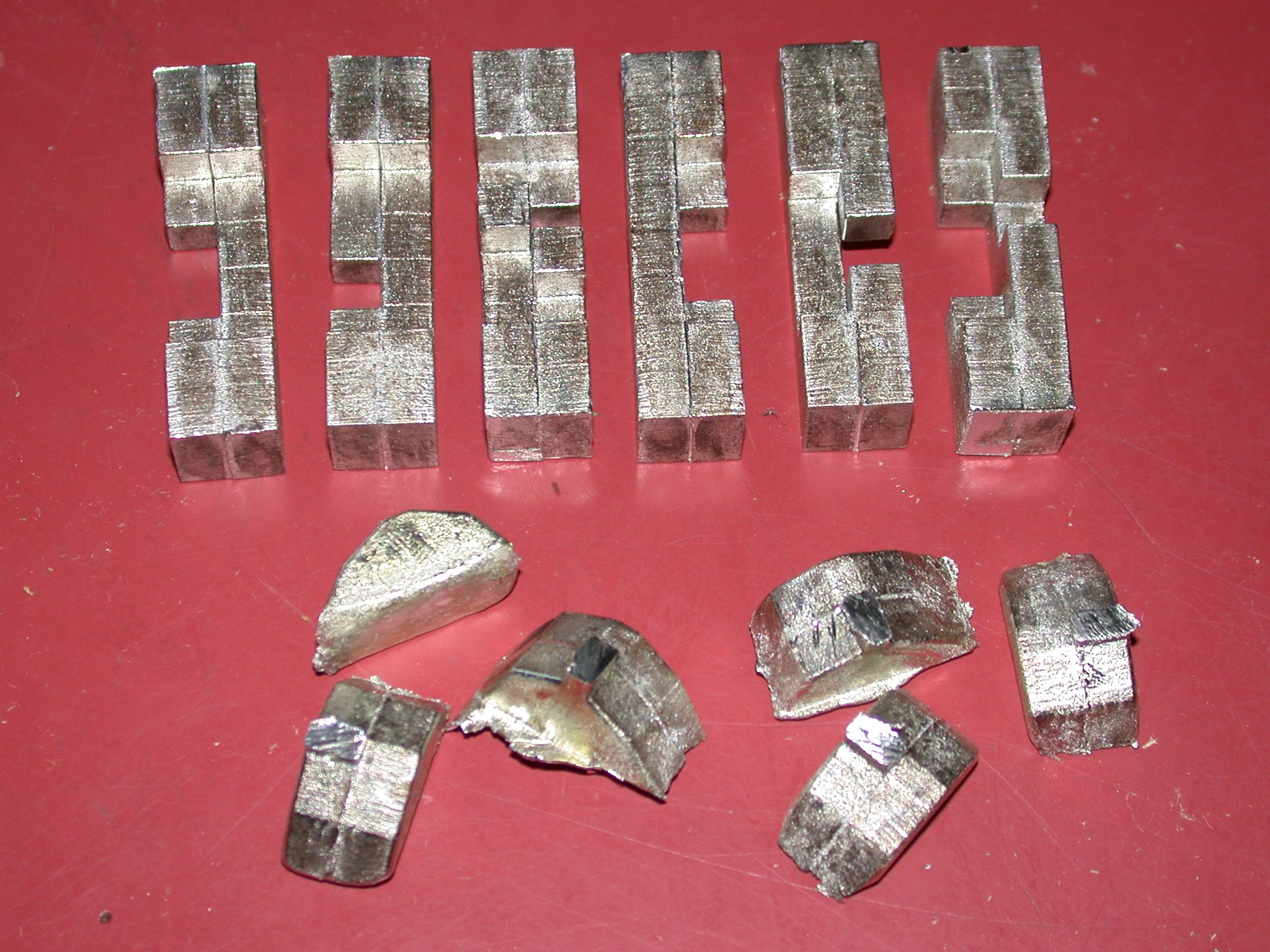
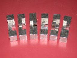
Cleaning up
After removing the cast entry points, the pieces still were a bit
stained by the resin that was emitted by the MDF and the edges
of the mold layers are rather visible. With a file I made the
mold layer edges a bit less obtrusive and using a steel brush I
removed all stains from the tin and gave the pieces a nice silvery
look. I brushed the sides of the pieces along their length axes.
The square top ends were brushed at 45 degree angles (with respect
to the sides of the top square). I expect that the silvery look
will wear off somewhat when the surface of the tin oxidizes.
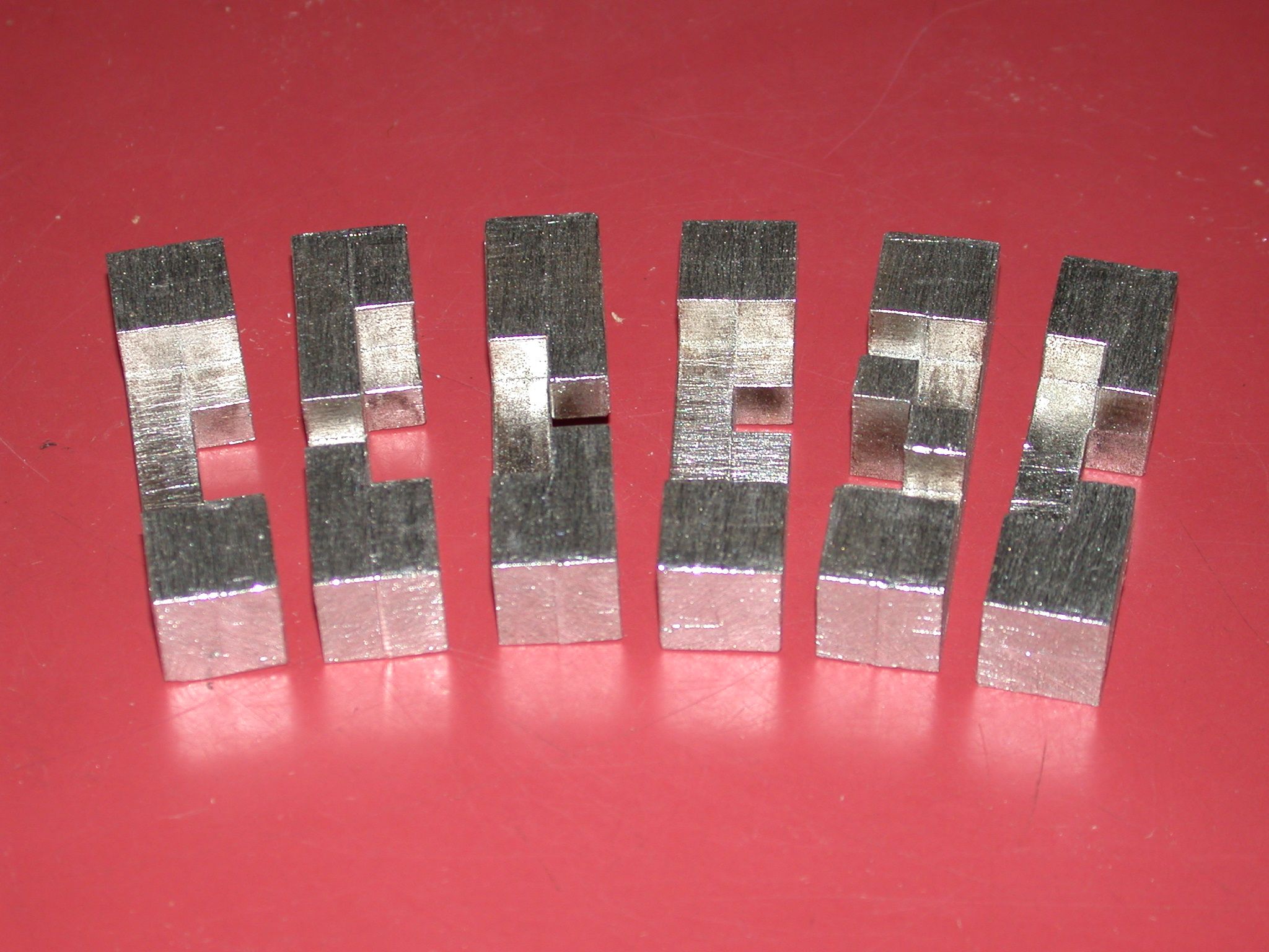
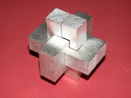
Assembled puzzle
Finally I assembled the puzzle. The pieces have a nice fit; I have
judged the thickness of the cut made by the laser well. The
assembled puzzle is shown below.
Peter Knoppers - (initial version: 2003-Sep-14, last edited: 2019-Jul-19)